Displaying Real-Time Spacecraft Communications with RasPi-Powered Wall Art

I’ve been working quite a while on a piece to hang up on my wall that displays – in real time – which spacecraft are communicating with NASA’s Deep Space Network. I finally got the prototype working and am excited to share the build process.

Background

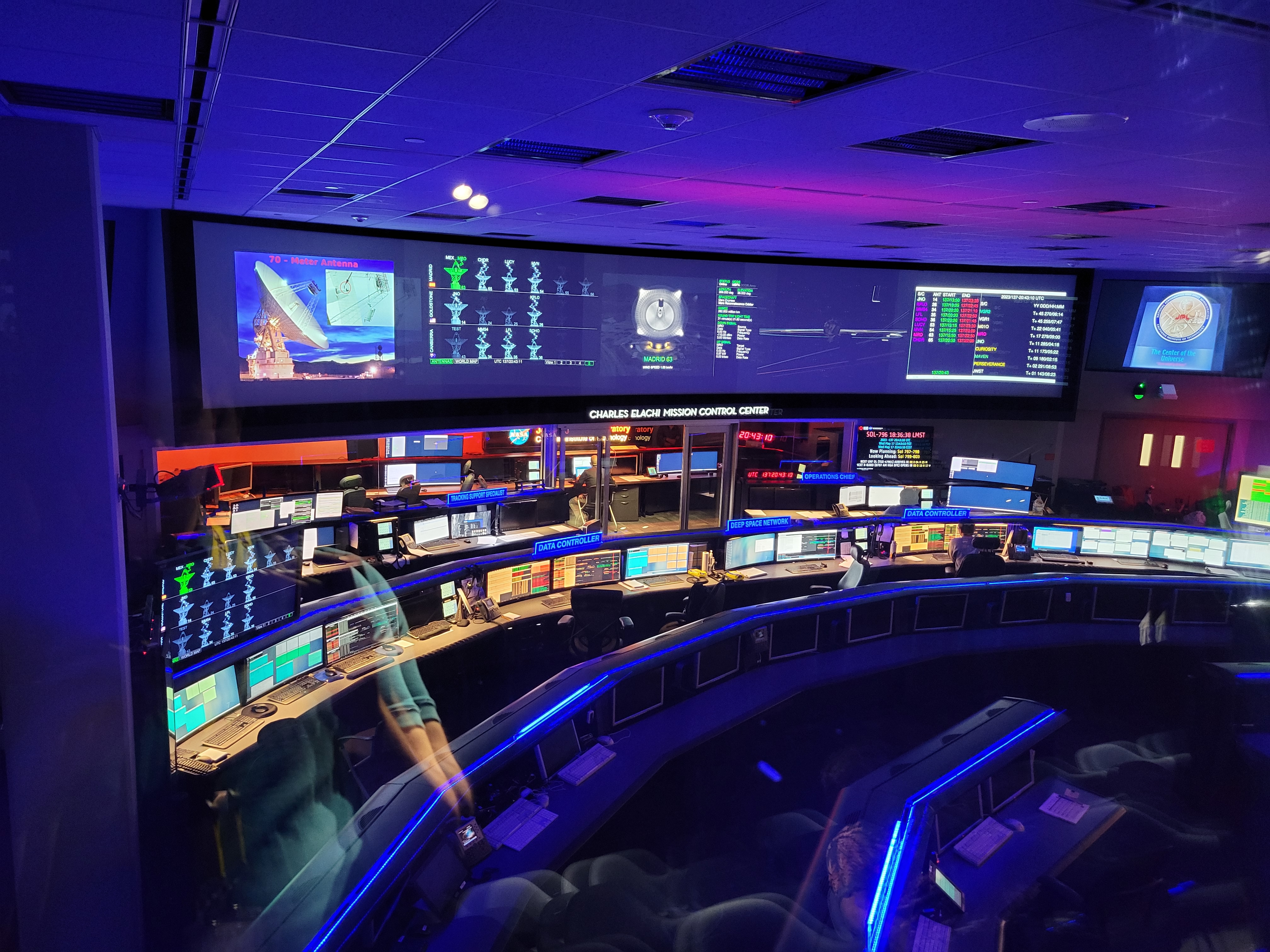
It is amazing that we humans can communicate with our robotic explorers across distances greater than the solar system itself. Voyager 1, now in interstellar space, is so far away that radio signals – traveling at the speed of light – take 22 hours to reach the probe and its responses a further 22 hours to return to us. As part of my job in the space communications field, I sometimes interact with NASA’s Deep Space Network (DSN). Headquartered at NASA’s Jet Propulsion Lab in California with major ground station sites in Spain and Australia, the DSN is responsible for communication with dozens of spacecraft across the solar system and (in the case of the Voyagers) beyond. This year I had the chance to see their impressive operations center.

NASA’s Deep Space Network Operations Center at the Jet Propulsion Lab

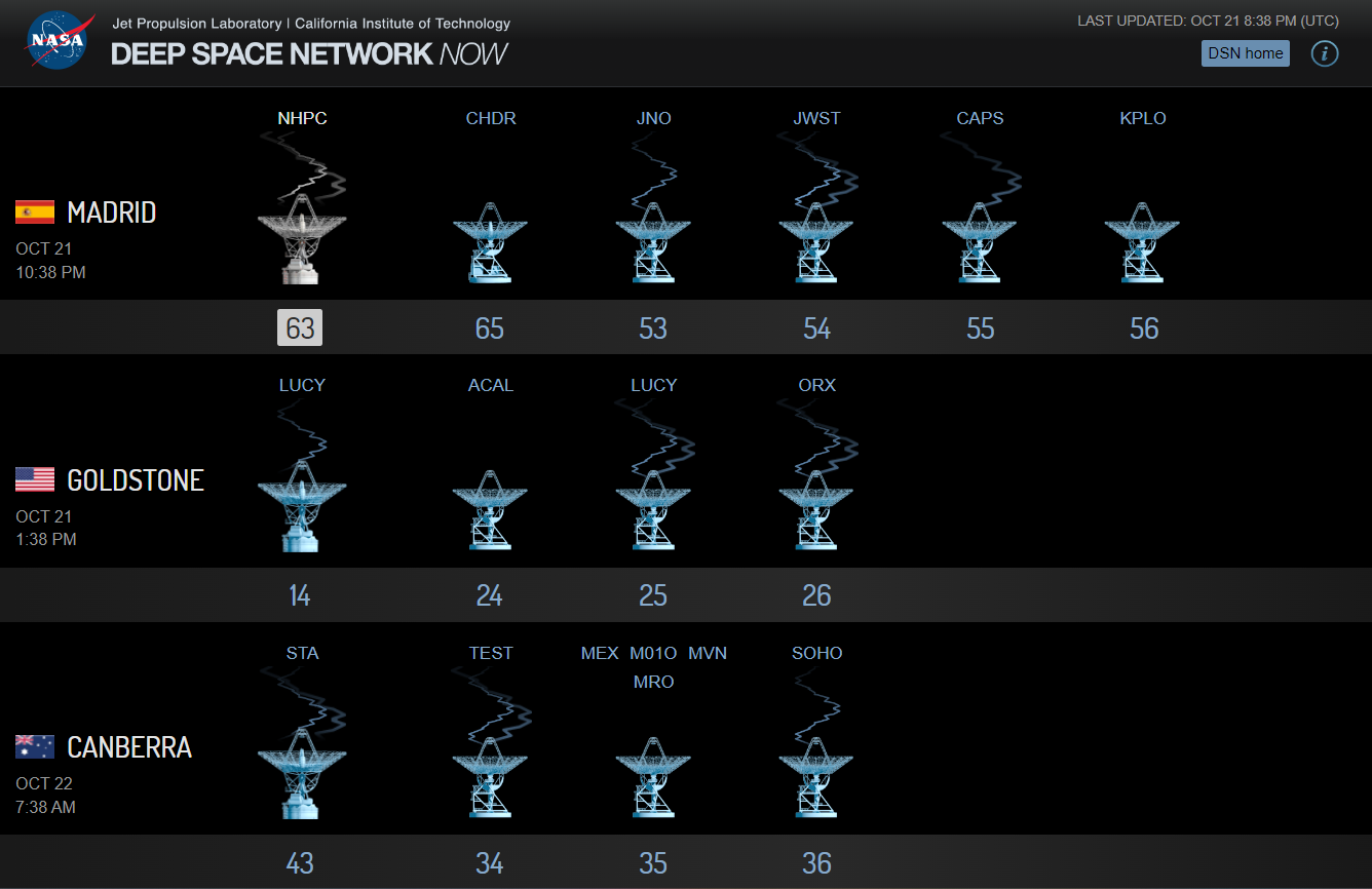
DSN also operates a very neat website which displays spacecraft that are communicating with each antenna – all in real-time. The display differentiates between carrier versus modulated data for both uplink and downlink.

Screenshot from the DSN Now webpage

What if, I thought, the information driving the website could be used to power a physical display to show the status of my favorite spacecraft in real-time? I would use LEDs to light up an image of each spacecraft while it was currently communicating. This could be hung on a wall and constantly run in the background as a neat reminder of our amazing capability to communicate across vast distances.
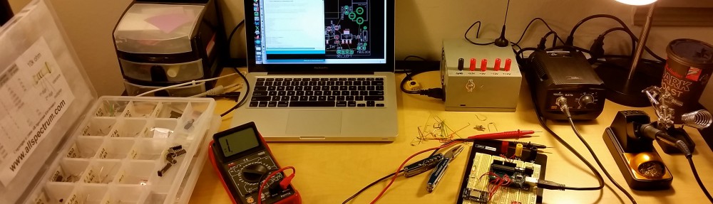
Hardware

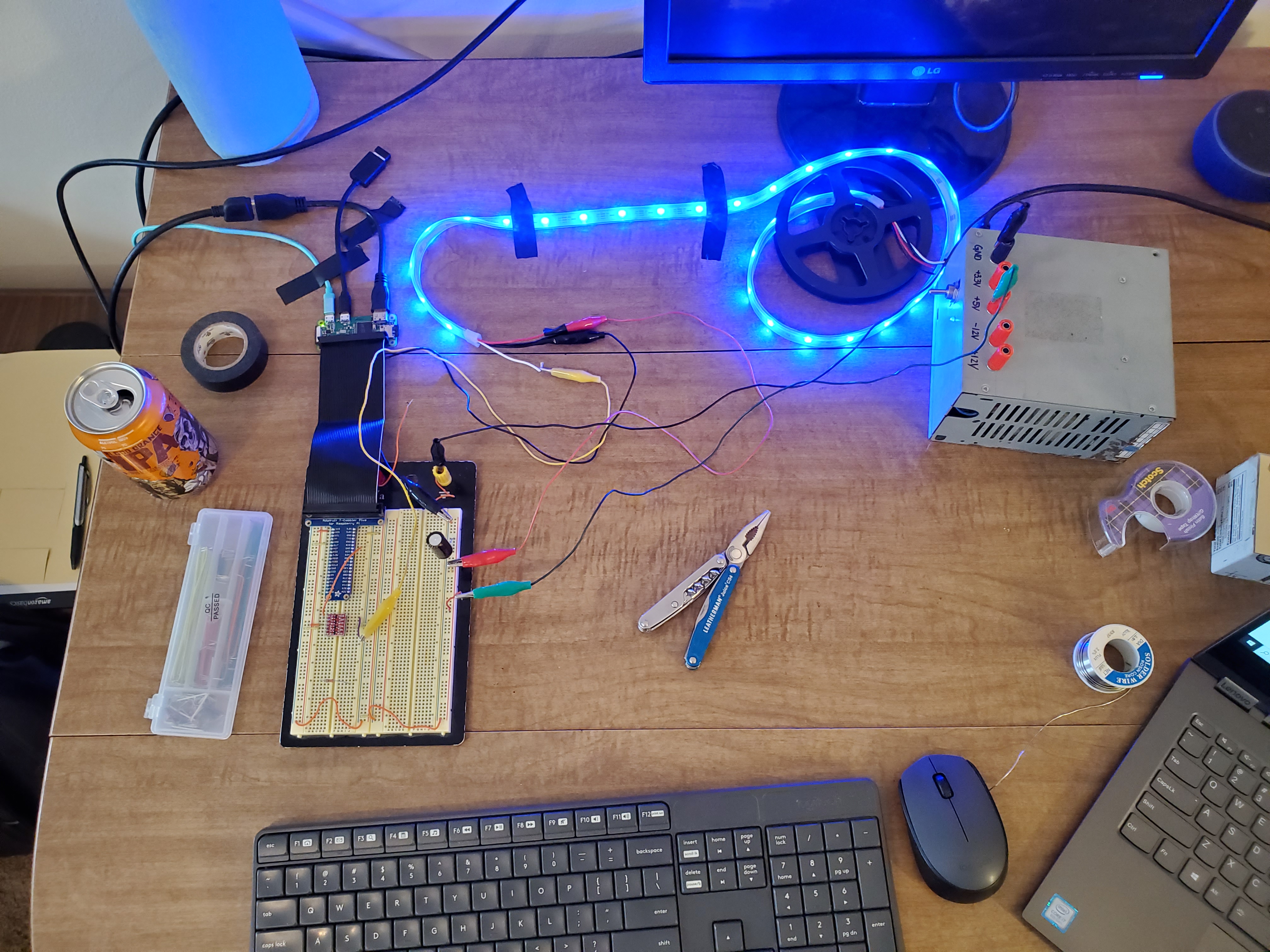
After the adventure of wiring 26 individual LEDs for my Stranger Things Halloween costume I knew I wanted to make things simpler with addressable LEDs. A strip of Adafruit’s NeoPixels were great for this. The strip has only three pins to wire: 5V, ground, and data. The data line connects to the controller chip inside each LED to command brightness and color.

I also decided to try a RasPi-based solution this time instead of using a microcontroller. The hardware timing wasn’t critical (plus Adafruit supplies a great Python library for NeoPixels that is Pi-compatible) and I’d benefit from having a full operating system to retrieve and parse data from the DSN. I went with the RasPi Zero W, a cheap model with a full WiFi stack built in. I also grabbed a GPIO breadboard breakout from Adafruit to help with prototyping.

NeoPixels saying “Hello World”

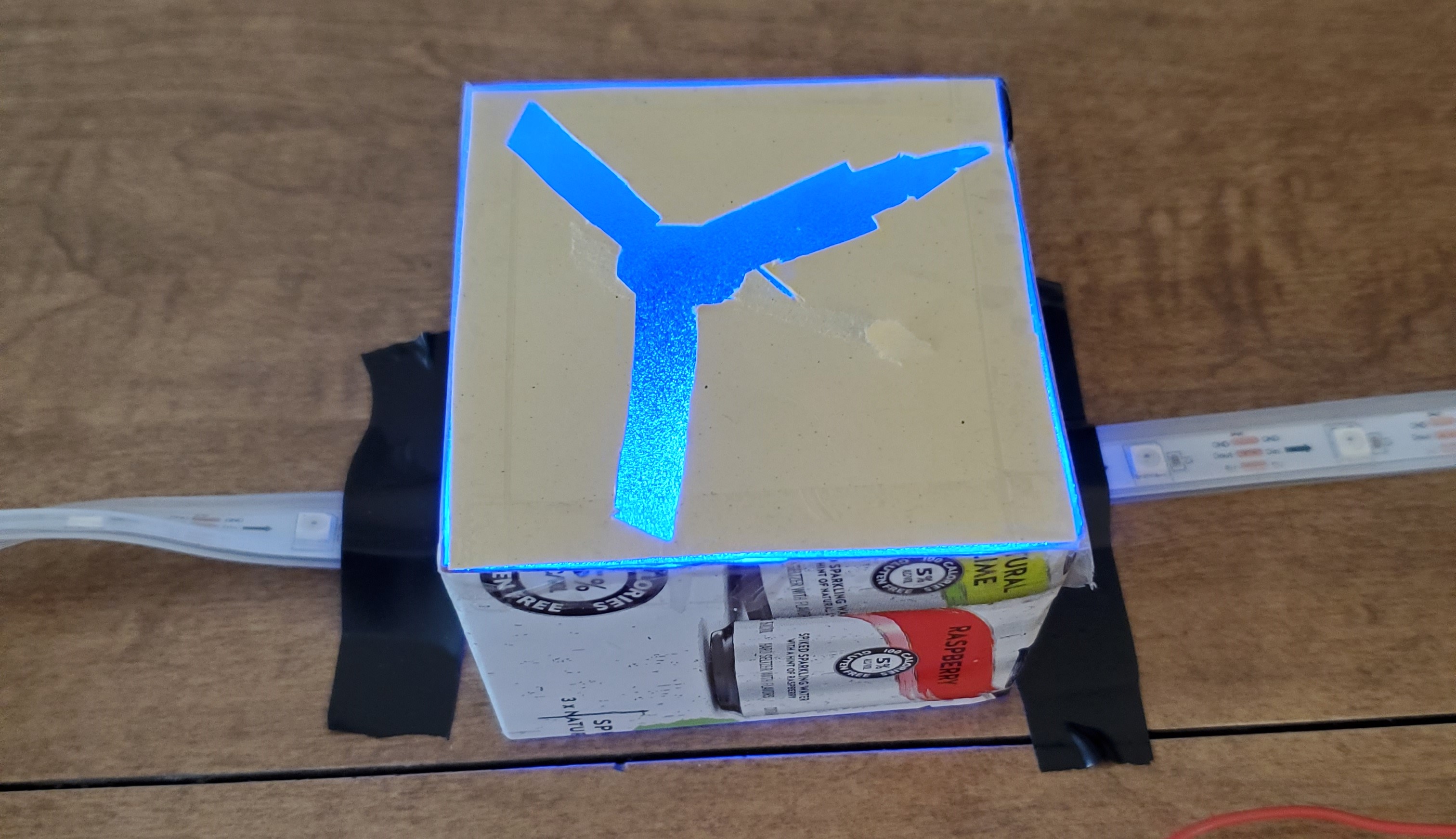
Rather than antenna-centric as the website, my build would pick several spacecraft and light up their silhouettes when active. After some quick prototyping, I landed on cutting the silhouette out of opaque material and using frosted vinyl (the kind you get to turn normal glass into a privacy window) to diffuse light from the individual LEDs. I found a good ratio was to have three LEDs illuminating a spacecraft image about 2″ wide.

Testing the look of LEDs illuminating a spacecraft silhouette.

Though the Pi is doing most of the heavy lifting, there are a few housekeeping items to take care of in the circuit:

  • I will be powering the strip and Pi with a 5V wall wart, but the Pi GPIO logic level is 3.3V. I’m using a Sparkfun logic level converter in the breadboard to step up the Pi’s 3.3V logic to the 5V which the NeoPixels expect.
  • The manufacturer recommends a large (1000μF) capacitor across the power supply and a 300-500Ώ resistor inline with the data pin.

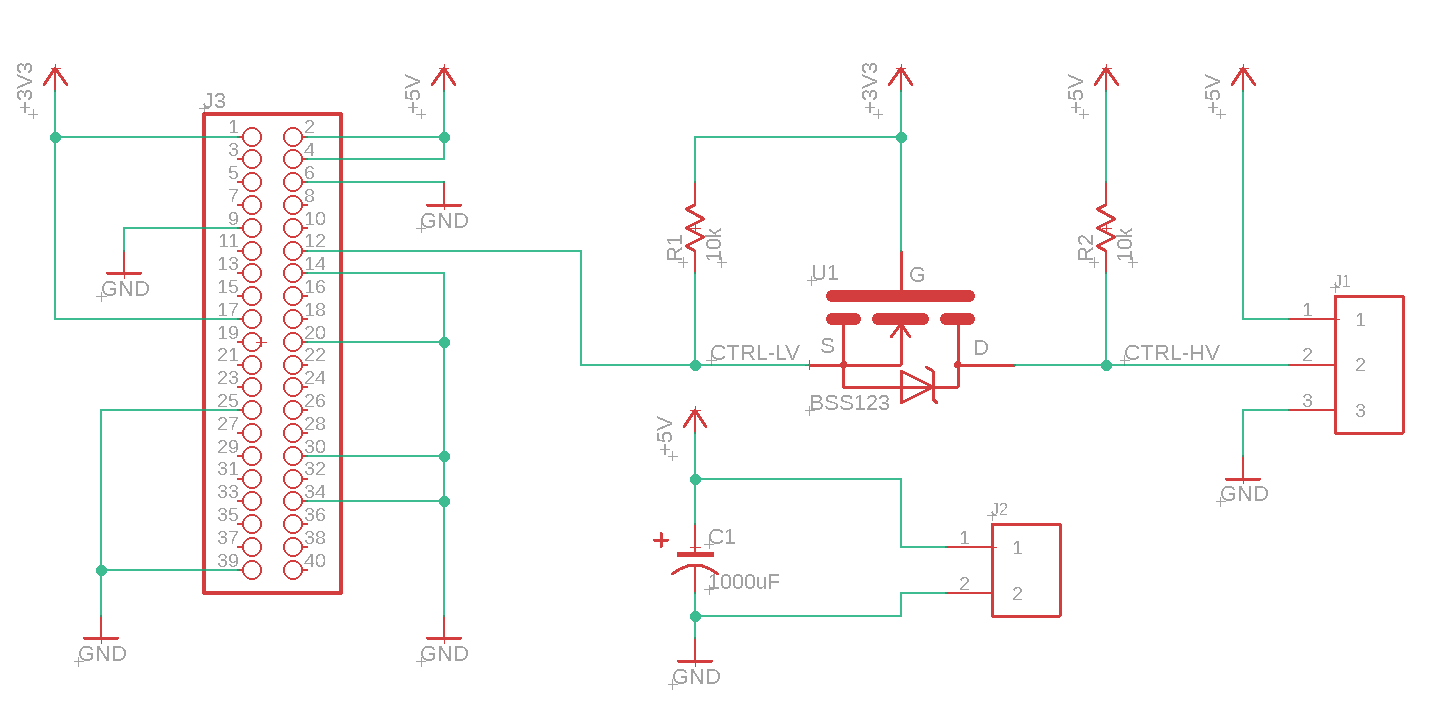
With the circuit working on a breadboard I created a PCB design which includes these components plus some screw terminals to connect the NeoPixel strip and a barrel plug for power. I implemented the same circuit as the Sparkfun logic level converter directly on the board with its component parts (a BSS123 MOSFET and some resistors).

Schematic view of my HAT for the Pi Zero

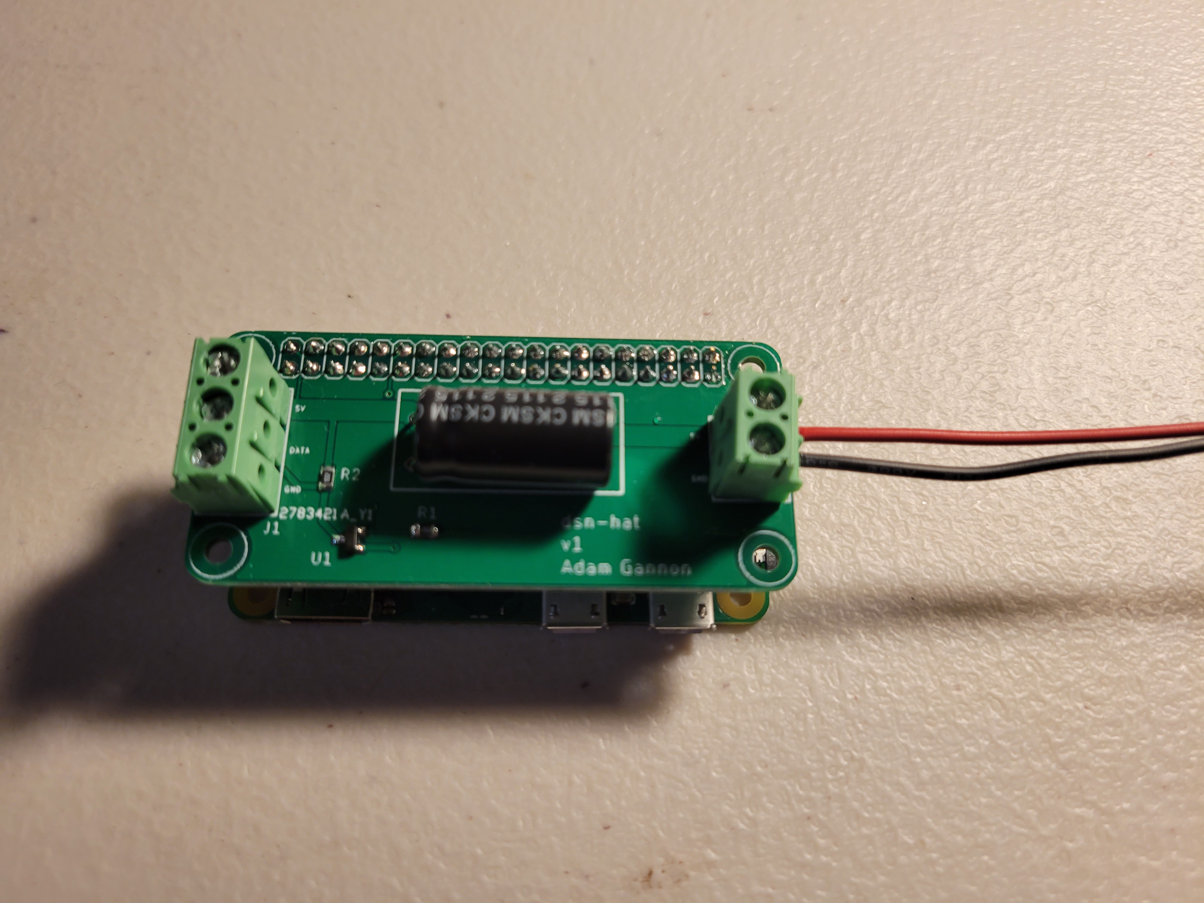
The board is shaped to be the same size as the Pi and connect through the 40-pin GPIO header. These application-specific boards that nest on top of a Pi are commonly called HATs. I sent the build to JLCPCB, who spun five boards for about $6 with shipping.

The populated board

Building The Frame

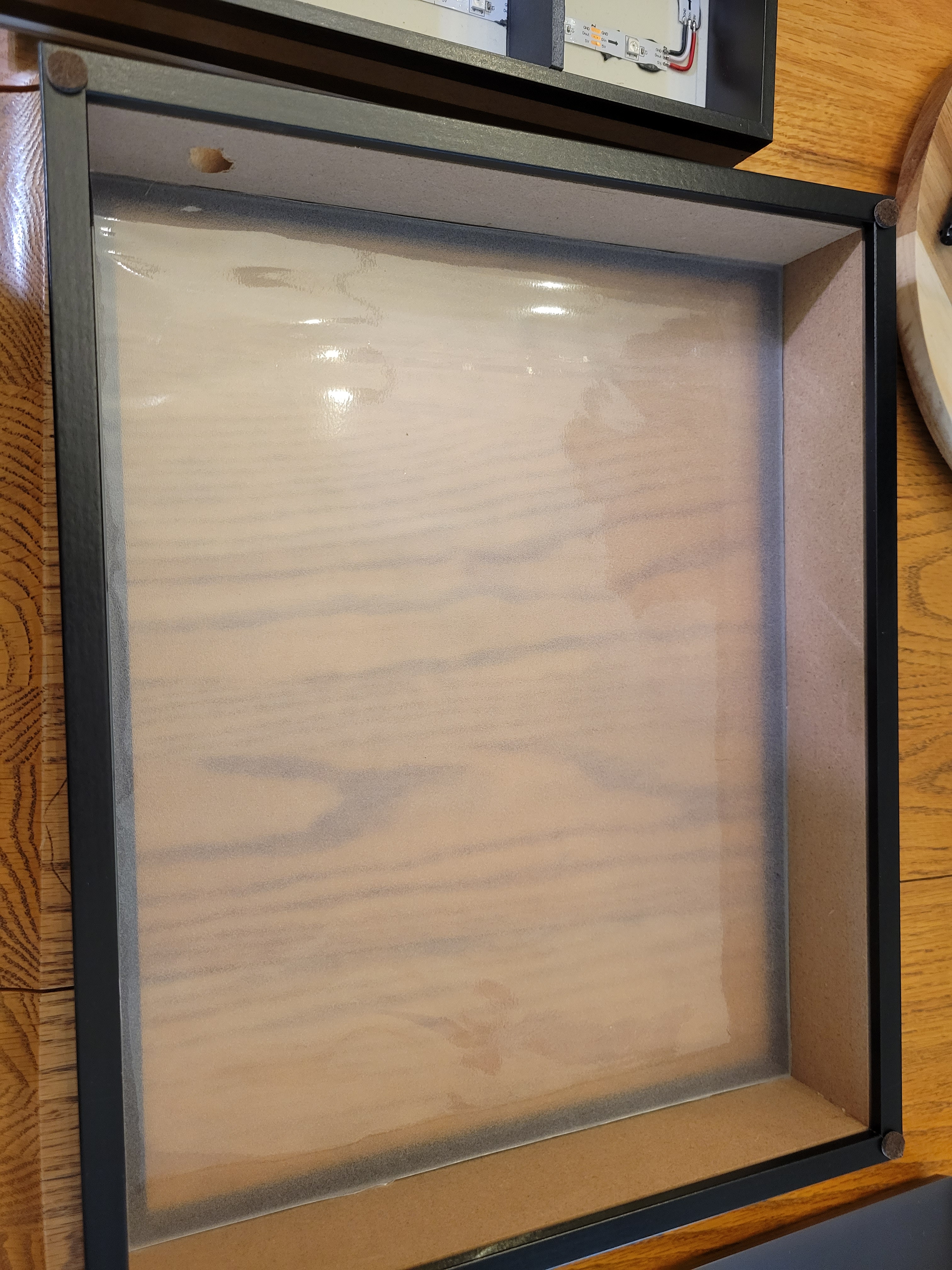
For the frame itself I got a shadowbox off Amazon. These are typically used for displaying items but I would use some foamboard to build up individual sections for each spacecraft’s LEDs. I started off by drilling a wide hole in the bottom of the frame to mount a barrel jack for power. A sheet of frosted vinyl was cut to cover the pane of clear glass for light dispersion.

Shadowbox with barrel jack mounting hole and frosted vinyl applied

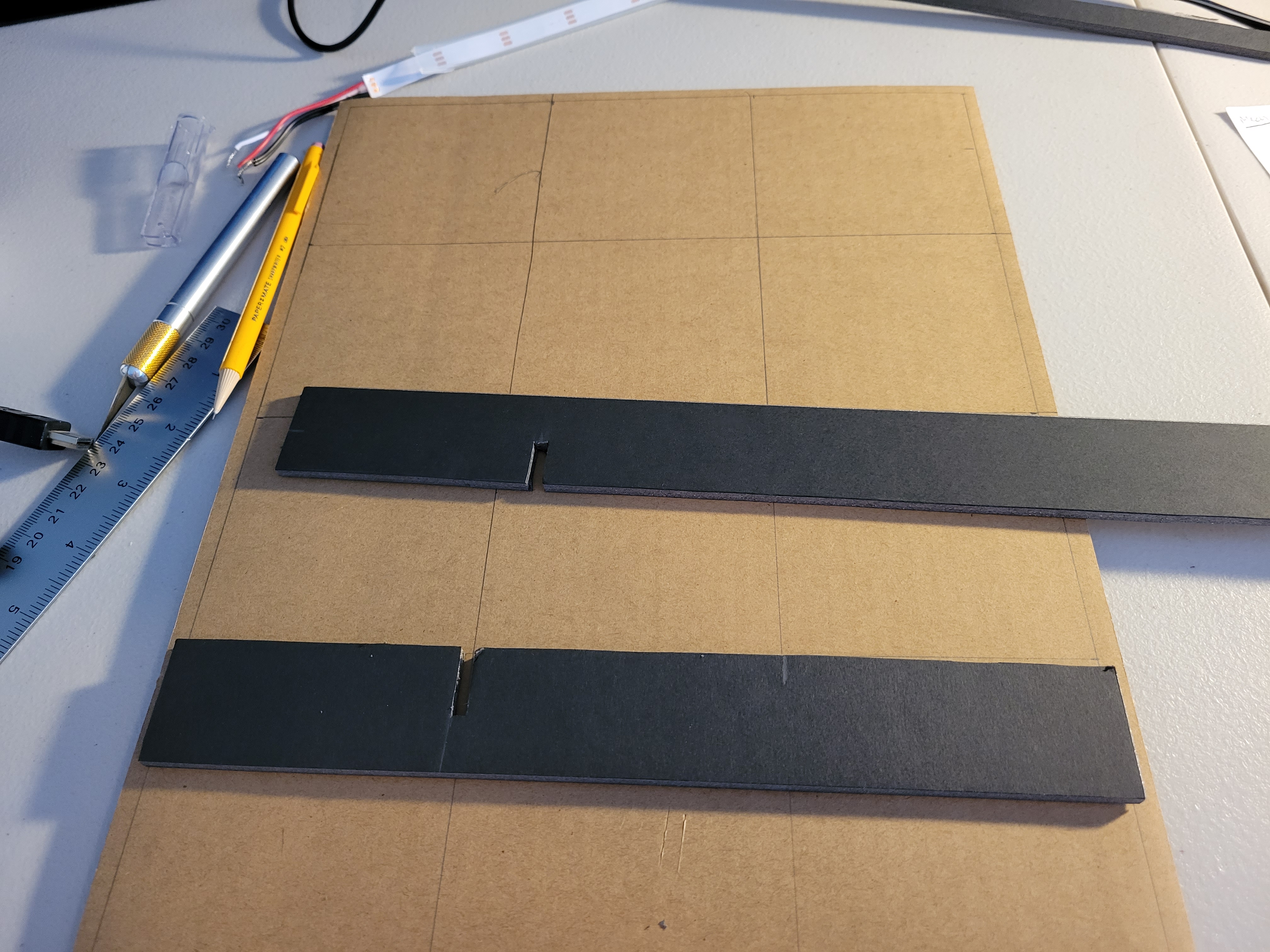
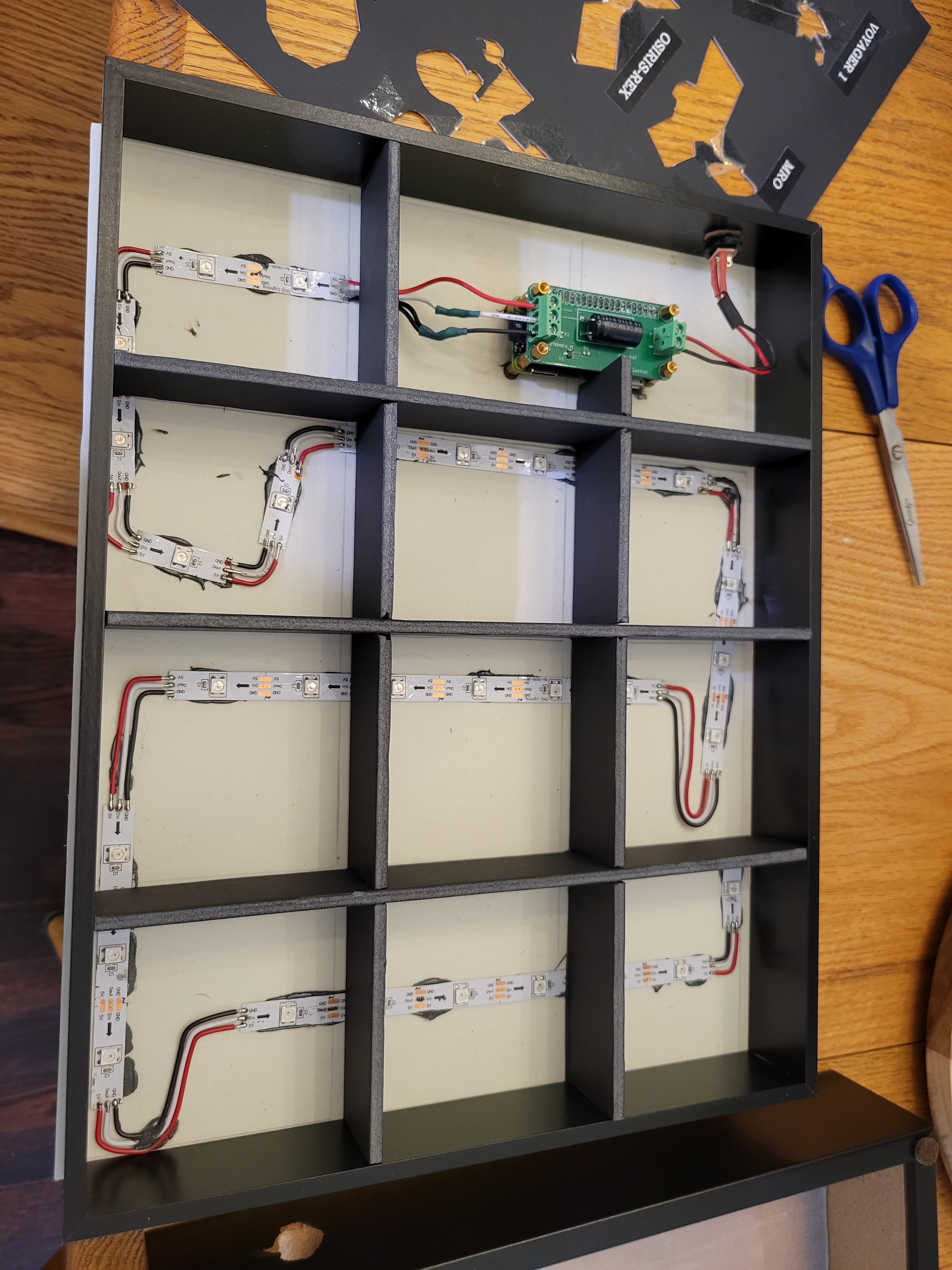
I cut some foam board into strips and notched it to build up a 3×4 grid to hold twelve spacecraft. Having a thick material as a divider was a must so light didn’t bleed over and illuminate adjacent spacecraft boxes.

Notching strips of foamboard
The grid built up inside the wooden frame

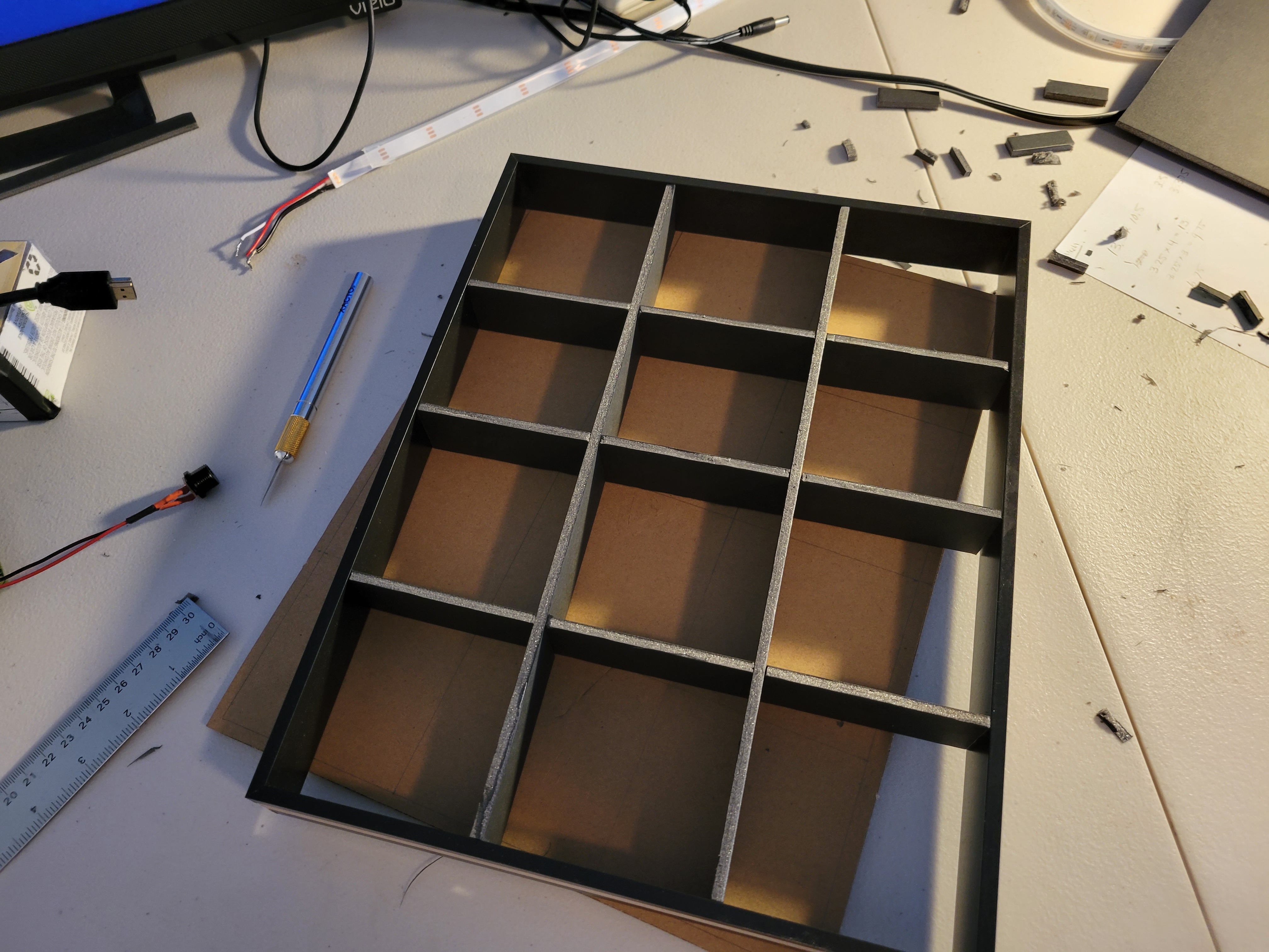
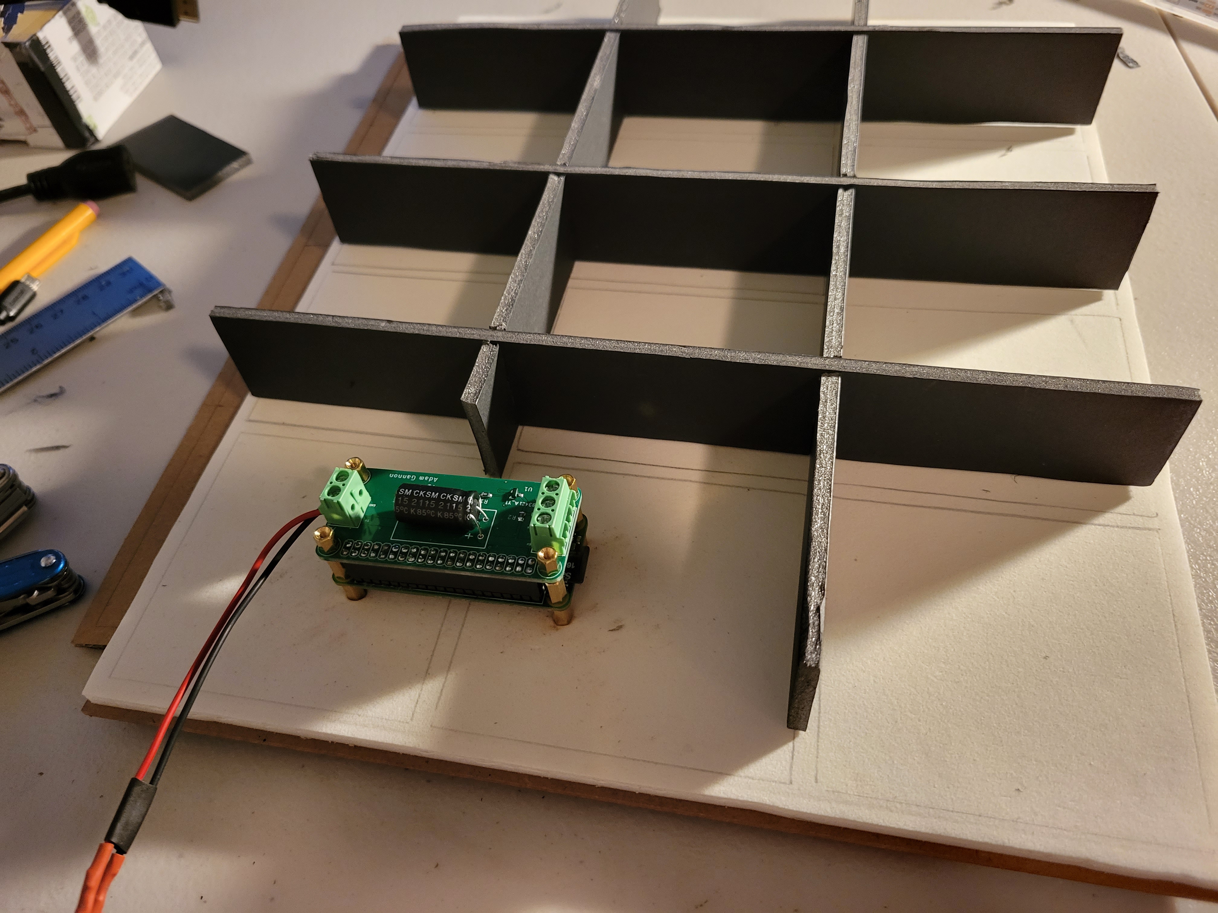
Unfortunately I had to give up two squares so I could mount the Pi in the frame. If I did this again I’d probably resize the grid to leave a more narrow space to fit the computer. I sunk some standoffs into the thick cardboard backside of the shadowbox. This gave the Pi a very secure mounting.

Pi mounted and the grid modified to fit.

Now it was time to mount the LEDs on the backing. I didn’t do a great job taking into account the spacing between LEDs when designing the grid. This required some bends and jumper wires to fit exactly three LEDs in each space while still tracing out the grid. The layout is basically the polar opposite of Design for Manufacturing, but it gets the job done. My glue gun was acting up when I went to tack down the LED strips so I went for the nuclear option of JB Weld epoxy. Those strips will be attached to this thing forever.

LED layout finished and board wired up

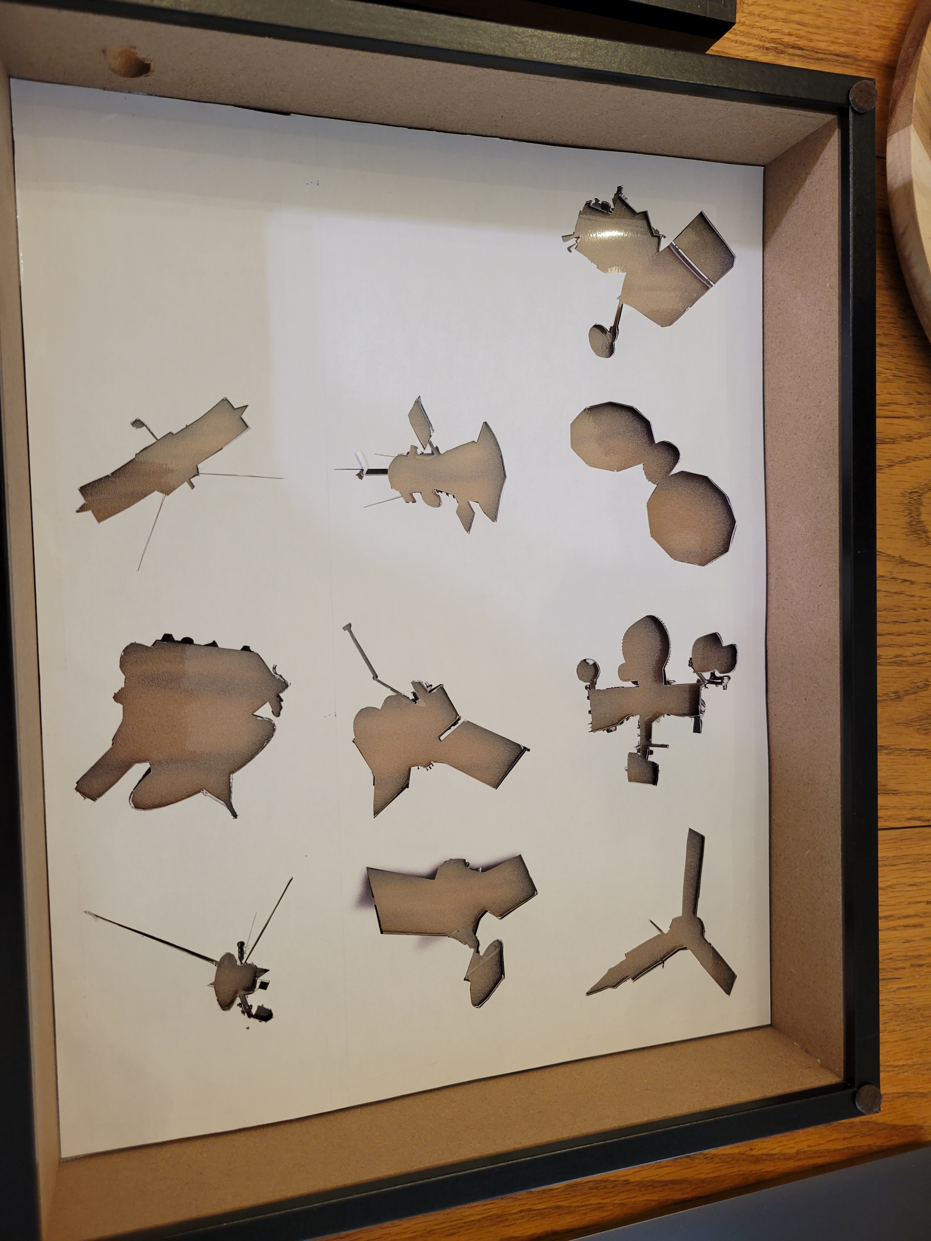
Finally I needed the silhouettes themselves. I grabbed images from NASA looking for spacecraft that will be flying for a while and had an outline that looked easy to cut out. These were printed on a large sheet of paper at the proper scale. I taped the stencil to a sheet of black posterboard and cut out each spacecraft shape. In the future I’d like to experiment with a CNC for this portion, but an X-Acto knife did the job pretty well. This sheet was layered behind the glass and vinyl. I printed some clear labels to identify each spacecraft.

Spacecraft shapes cut out

Software

Step one for the code was to parse data on the DSN website. A super helpful start was Russ Garrett’s GitHub repo which powered the @dsn_status Twitter bot before some API changes broke it a while ago. With only a few changes, I used a version of the module to parse the site’s XML into a nested dict.

Data on the DSN site is organized by antenna. Each antenna has status on its uplink, downlink, and the target spacecraft (in some cases a single antenna can receive signals simultaneously from multiple spacecraft within view). Each time the main loop runs, I iterate through the antennas and find the antennas which are communicating with the 10 spacecraft on the board. From that antenna I pull its uplink/downlink status.

 # Init a dictionary from our spacecraft list to hold parsed status.
 sc_update = dict.fromkeys(hardware.spacecraft, Status.OFF)

for ant in data.keys():
    # Get targets (can be multiple). Filter out 
    # any targets that aren't on the board
    targets_raw = list(data[ant]["targets"].keys())
    targets_low = [x.lower() for x in targets_raw]
    filt_targets = [x for x in targets_low if x in hardware.spacecraft]
        
    for spacecraft in filt_targets:
        status = calc_status(data[ant])
        sc_update[spacecraft] = status

I defined a set of colors for each possible status. The both options are set if both the uplink and downlink are in the same mode (e.g. carrier or data). Each tuple is a red, green, blue (RGB) triplet that defines the intensity of each primary color in the LED. If the spacecraft is not found on the active list, the default status is off. I went for a blue/purple color scheme, but this can be easily reconfigured if I want to switch it up.

class Status(Enum):
    """RGB triplet for each type of spacecraft status."""
    OFF = (0, 0, 0)
    UP_DATA = (0, 235, 145)
    DOWN_DATA = (0, 130, 235)
    BOTH_DATA = (225, 0, 235)
    UP_CARRIER = (0, 0, 235)
    DOWN_CARRIER = (0, 0, 235)
    BOTH_CARRIER = (0, 0, 235)

The final step is to update the LEDs. I defined a hardware mapping dict which specifies which LEDs correspond to each spacecraft silhouette. Using this I can set the LEDs for a spacecraft to the RGB value set by the current status. I wrap this in a helper class, but the NeoPixel library does the heavy lifting to communicate with the LED controller chips.

class Leds:
    """Manipulate LEDs."""
    
    def __init__(self):
        self._pixels = neopixel.NeoPixel(board.D18, 30)

    def set_group(self, pins, status):
        """Set each pin in the list pins to the
        RGB triplet contained in status."""
        for pin in pins:
            self._pixels[pin] = status.value
            logger.debug(f"LED #{pin} to {status.value}")

Finally, a few housekeeping things. Execution of the loop only takes tens of milliseconds so a sleep every loop prevents me from hammering NASA’s website. Contacts are tens of minutes, so this can be a fairly lengthy sleep and not miss much updating. I also don’t need the LEDs on all the time, especially when I’m sleeping. This was the first time I exercised argparse’s ability to accept a custom function as a type argument. Here I’m having it convert a string time window into a pair of datetimes. When the RasPi’s system time is outside this window I turn off the LEDs.

  def main():
    # Set up argument parser
    parser = argparse.ArgumentParser() 

    # Allow operation within a time window.
    default_window = parse_time_window("08:00-22:00")
    parser.add_argument("--window", type=parse_time_window,
    default = default_window,
    help = "Time window to display LEDS in 24 hour HH:MM-HH:MM format.")

def parse_time_window(input_str):
    try:
        start_str, end_str = input_str.split('-')
        start_time = datetime.strptime(start_str, "%H:%M")
        end_time = datetime.strptime(end_str, "%H:%M")
        return start_time, end_time
    except ValueError:
        raise argparse.ArgumentTypeError("Invalid time window format.")

With the code complete, I packaged it up as a pip-installable package dsn-leds. Adding this to /etc/rc.local will start the script on boot, where it will run indefinitely.

Testing & Mounting

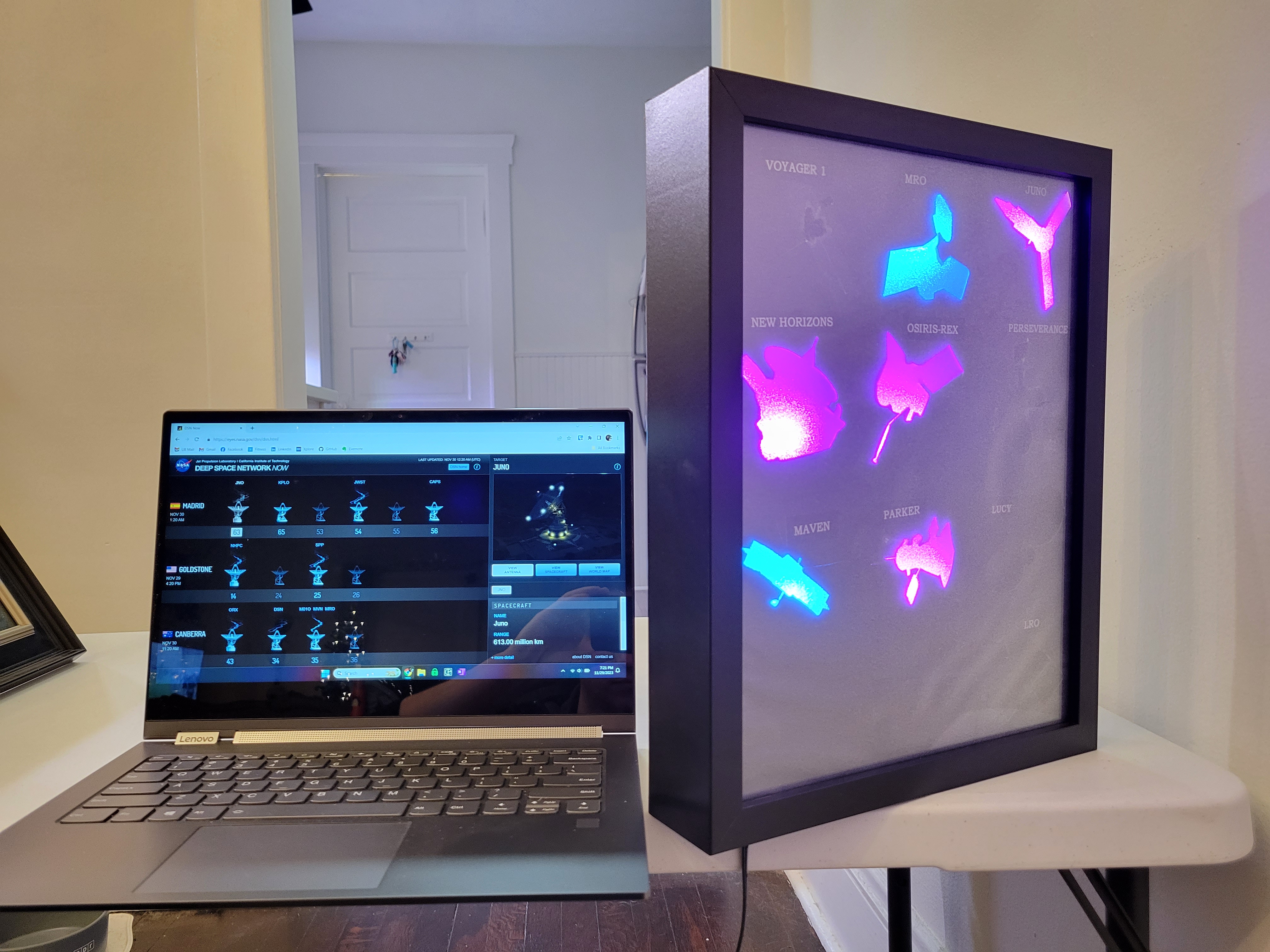
With the code complete I can check against the DSN website to verify everything is working. In the screenshot taken below there are 11 spacecraft listed:

  • Maven and MRO are in downlink data mode (blue on board).
  • Juno, New Horizons, Parker, and OSIRIS-REx are sending data bidirectionally (purple on the board).
  • James Webb, Mars Odyssey, Kepler, and CAPSTONE are active but these spacecraft are not on my board.
  • DSN is used for testing, per the website.
Testing the LED board against the DSN Now website

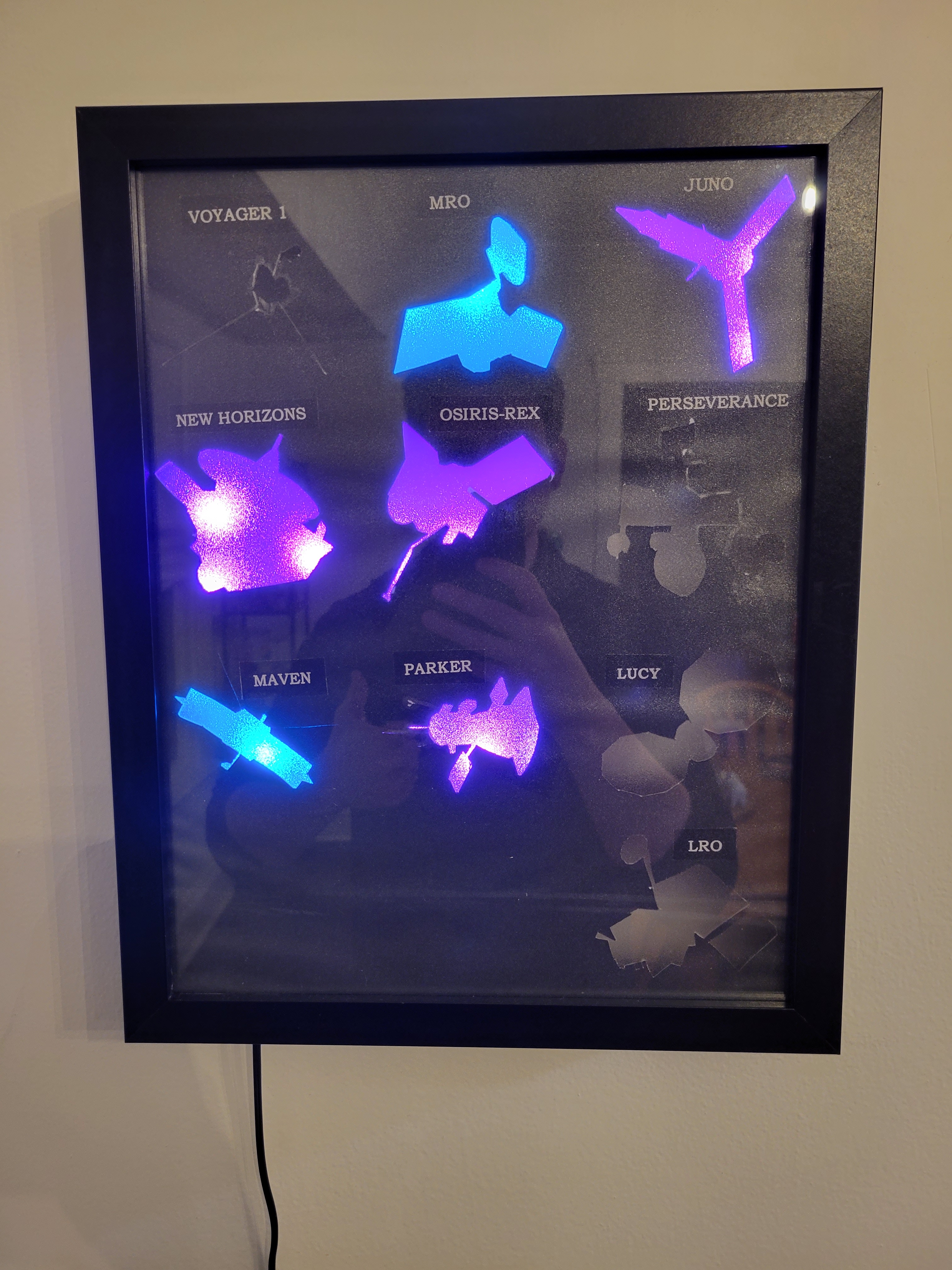
And it looks pretty good mounted on the wall!

The finished product

Full code for this project is available on my GitHub.

Automated Watering System to Keep House Plants Alive

I learned from my girlfriend, a self-described plant person, that I’ve probably killed most of my plants from giving them too much water rather than not enough. However, our plans to be out of town for several weeks were going to be too long for her several houseplants to go without water. My solution: a timer-controlled water pump that can be adjusted to provide the right amount of water to several plants at regular intervals!

Components used in this project were:

  • Arduino Uno – the brains of the operation
  • HD44780-based 2×16 LCD screen – for data display
  • PEC11 Rotary Encoder – for user input
  • PCF8523 Real Time Clock (RTC) – for accurate timekeeping
  • 5V submersible water pump – this will actually go in the water source
  • 5V relay module – to control the pump
  • Screw potentiometer – to adjust LCD brightness.

Background

I started this project thinking I would measure soil moisture and release water automatically. There are plenty of kits online that sell cheap PCBs shaped like a tuning fork for this purpose. These act as a potentiometer with resistance varying with moisture. Unfortunately they’re just not very accurate and worse the exposed metal corrodes over time. Supposedly capacitive sensors are better in this regard but I realized measurement isn’t very necessary. All our houseplants are watered on a schedule anyways, so I just needed a way to automate that.

Concept of Operations

The user configures how often they want the plant watered and how much water to use. Settings are selected by turning the rotary encoder and confirmed with a push. These settings translate to a time and duration to run the pump for. I did some experiments to measure the flow through the pump and found it conveniently moves about 1oz of water every 1 second.

The internal oscillator on the Arduino board will lose several minutes per day. While this is not a big deal for our application, I decided to add a Real Time Clock (RTC) module to the build. Accuracy loss on this device is several seconds per month! The big advantage is that the RTC can generate an interrupt on a configurable interval (I chose 10 seconds) to wake the board up.

After settings are confirmed, the unit goes into sleep (SLEEP_MODE_PWR_DOWN) until the RTC interrupt fires. If it’s not time for watering yet the unit repeats the sleep cycle. In theory this should make it low power enough to run off a 9V battery, though in our installation we used a USB cable and wall wart for power.

The pump is submerged in a vase of water. When time for watering, a digital output pin from the Arduino trips a relay which powers on the pump for the required duration (using 1s = 1oz). After watering is complete, a timer is set for the next watering interval and the unit sleeps again.

Wiring & Build

Sketch of wiring diagram between Arduino and major components.

I house the electronics in a simple project box and made the cutouts by hand with my Dremel. Boards were mounted using screws and standoffs. Admittedly the hand drilling and screws aren’t aesthetically pleasing, but I wasn’t going for looks in this project. The relay didn’t have mounting holes, so I used double-sided Velcro to mount it to the side.

I used some Arduino-shaped perfboard (sometimes called a Proto Shield) to mount the RTC and potentiometer for LCD brightness adjustment. Since it was inside, the LCD wouldn’t be user adjustable, but I really just needed to put it at a good set point once. I didn’t have a full ribbon cable for the LCD which made the wiring messier than desired, but all the connections were made following the above diagram without issue.

I wanted the pump wired so that it could be disconnected to move easily. I soldered the leads of the pump itself into a barrel plug and fitted the side of the project box with a barrel connector. With that it was ready to go!

Completed box with pump (left) and USB power (bottom) connections.

Code

The encoder knob was straightforward to work with using the encoder library. I found the knob quite sensitive so I adjusted the read logic to require four clicks to change a value.

int incrimentEncoder(int inc)
{
  long newPosition = enc.read();
  if (newPosition != oldPosition) 
  {  
    if ((newPosition-oldPosition)>=4)
    {
      oldPosition = newPosition;
      return inc;
    }
    else if ((oldPosition-newPosition)>=4)
    {
      oldPosition = newPosition;
      return -inc;   
    }
  }
  return 0;
}

Settings were applied by pressing the encoder knob down, which was measured by a digital input (buttonPin). I just had to implement a simple debounce routine.

/*  Check state of rotary button
 *  Return TRUE if button has been pressed
 */
bool buttonPressed()
{

  // No press detected, by default 
  bool returnState = false; 
  
  // Get current reading 
  int reading = digitalRead(buttonPin);

  // If the switch changed, due to noise or pressing:
  if (reading != lastButtonState) 
  {  
    // reset the debouncing timer
    lastDebounceTime = millis();
  }

  // Debounce 
  if ((millis() - lastDebounceTime) > debounceDelay) 
  {
    if (reading != buttonState) 
    {
      buttonState = reading;
      
      // Push is low, so register if pushed 
      if (buttonState == LOW)  
      {
        returnState = true;
      }
    }
  }
  
  //Store variable 
  lastButtonState = reading;
  return returnState;
}

The majority of the logic in the code has to do with moving through the screens to configure watering time and duration. The Liquid Crystal library helped here.

Finally, I needed to set up the sleep routines. This started by configuring the RTC in the setup routine, by using the RTC library.

  rtc.deconfigureAllTimers();
  rtc.enableCountdownTimer(PCF8523_FrequencySecond, 10);  // 10 seconds

An interrupt was attached to the 10 second timer from the RTC as well as the encoder button press, so the user could wake the unit up at any time.

void enableSleep()
{
  // Attach interrupts and make sure they have time to register before sleep
  attachInterrupt(digitalPinToInterrupt(sqwPin), timerIsr, FALLING);
  attachInterrupt(digitalPinToInterrupt(buttonPin), buttonIsr, FALLING);
  delay(100);

  timerFired = false;
  buttonFired = false;

  // sleep_mode() is a blocking call
  set_sleep_mode(SLEEP_MODE_PWR_DOWN);
  sleep_enable();
  sleep_mode();

  sleep_disable();
  detachInterrupt(digitalPinToInterrupt(sqwPin));
  detachInterrupt(digitalPinToInterrupt(buttonPin));
  Serial.println("morning.");
}

The variables timerFired and buttonFired are set in their respective interrupt service routines (ISRs) and checked in the main loop to take action. Each time the timer interrupt fires, we compare the current time against the time of the next watering and switch the relay on if it’s time to water.

void checkTimer()
{
  DateTime now = rtc.now();
  if (now > nextWatering)
  {
    Serial.println("WATERING");
    // Water now
    triggerRelay();
    delay(1000);
    lcd.begin(16, 2);
    lcd.clear();
    lcd.print("Done.");
    delay(1000);
    // Update timer for next watering interval 
    setNextWatering();
  }
}

The full code is available on GitHub.

The Test

After some checkout tests, the setup was ready for primetime. We connected the pump output through a small section of tubing into the pot. After two weeks away, the Bird of Paradise was well-watered and doing great when we returned!

The watering setup and a happy BoP.

Making my dumb air conditioner smart with Alexa and Adafruit IO

New “smart” air conditioners are internet-enabled allowing control anywhere via smartphone or voice assistant. Using a microcontroller, infrared (IR) LED, and several plug-and-play frameworks for the backend I was able to replicate the same functionality on my 10-year-old “dumb” air conditioner. I can now power it on/off with my voice and even turn the unit on from my phone so it is cool when I arrive home!

Major components used in this project were:

In short, the IFTTT skill for Alexa was used to relay my voice command to the Adafruit IO platform. My Arduino, connected to the Internet via the WiFi board and running the client software for Adafruit IO, sent the IR signal to power on the AC when the command was received.

Block diagram of connections between components.

Duplicating the Remote

My AC came with a small IR remote. First order of business was decoding the signal it sends when the power button is pressed so it can be played back from my custom circuit. Unlike other remotes that use a rolling code for security, the AC remote simply sends the same sequence each time.

A simple circuit with a TSOP382 IR receiver diode is connected to a digital input pin on the Arduino. Air conditioners tend to use longer control sequences than other IR devices, which was a problem for several decoder libraries I tried. I was able to decode the full sequence using this sketch from AnalysisIR.

I added a IR LED connected to one of the digital outputs through an NPN transistor to send IR signals from the Arduino circuit. The IRremote library was used to play back the raw sequence, which turned the AC on as expected!

Original air conditioner remote and IR receiver diode circuit to read its signal.

Connecting the Remote to the Internet

I created an account on Adafruit IO and set up a Feed called "Air Conditioner". The companion Arduino library uses the ESP32 WiFi module to connect to the Adafruit IO servers, listens for messages from that feed, and triggers a handler function in response to an incoming message.

// Set up the Air Conditioner feed 
AdafruitIO_Feed *acFeed = io.feed("Air Conditioner");

void setup() {

  // Start serial and connect to io.adafruit.com 
  Serial.begin(115200);
  while(! Serial);
  Serial.print("Connecting to Adafruit IO");
  io.connect();

  // Hanlder function for the "Air Conditioner" feed from Adafruit IO. 
  acFeed->onMessage(handleMessage);
}

I then created a Dashboard button on Adafruit IO to publish to the Air Conditioner feed. Since I only cared about the trigger, the button sets the feed’s value to ‘1’ each time. With everything connected, I verified I could power the AC on by pressing the dashboard button.

Plumbing the Back End

Just a few more setup items were required to connect commands from Alexa to Adafruit IO. I mostly followed this guide which outlined:

  • Installing the IFTTT Alexa skill and assigning a trigger phrase (I used "air conditioner")
  • Adding Alexa and Adafruit IO services to my IFTTT account
  • Setting up the "Send Data to Adafruit IO" action in IFTTT.

With everything in place, I was able to use voice commands to trigger the AC unit, as shown in the above video! As always, the code is available on GitHub.

Full circuit.

Autogenerating a block for each data type in GNU Radio using the GR_EXPAND utility

Many of the blocks in GNU Radio allow the user to select what data type (complex, float, int, byte, etc.) the block operates on. Writing a new block to handle each data type would be tedious, so the framework includes a utility to generate a number of different blocks from template files. I’ve used this to handle different data types in my message utility blocks and some research projects. While useful, I haven’t seen a lot of out-of-tree projects use it so I thought I’d add a step-by-step guide to using the utility for your own out-of-tree blocks.

Background

One may notice that many of the blocks in GNU Radio Companion include an option to configure the data type (complex, float, int, byte, etc.) that the block uses, often with a parameter called “IO Type”:

Screen Shot 2017-05-20 at 11.44.30 AM

The Add Const block supports several data types

Looking at the relevant parts in the block’s XML definition file we see that the option is used to call a different block for each data type

blocks.add_const_v$(type.fcn)($const)
...
 <param>
   <name>IO Type</name>
   <key>type</key>
   <type>enum</type>
   <option>
     <name>Complex</name>
     <key>complex</key>
     <opt>const_type:complex_vector</opt>
     <opt>fcn:cc</opt>
   </option>
   <option>
     <name>Float</name>
     <key>float</key>
     <opt>const_type:real_vector</opt>
     <opt>fcn:ff</opt>
   </option>
...

For example, selecting the complex option causes GNU Radio to call blocks.add_const_vcc whereas the float option will call blocks.add_const_vff. So where are those defined?

Though they are separate blocks in the view of GNU Radio, each was generated from a common file. Looking in the gnuradio/gr-blocks/lib directory we see the files add_const_vXX_impl.cc.t and add_const_vXX_impl.h.t which are the template files for each block. There is a similar add_const_vXX.h.t in the gnuradio/gr-blocks/include/gnuradio/blocks directory. Taking a look at the CMakeLists.txt shows the commands to generate the blocks.

include(GrMiscUtils)
GR_EXPAND_X_H(blocks add_const_vXX bb ss ii ff cc)

At compile time, the appropriate files will be generated from the templates and compiled. After that, they can be called from a Python or GNU Radio companion like any other block.

Let’s Build Our Own

There are a few steps to using the utility in your own out-of-tree projects, so let’s go through them step-by-step. Following the steps of the GNU Radio tutorial for writing out-of-tree modules we’ll create a block that performs a simple squaring operation. We’ll go through the process step-by-step, but the end result can be downloaded from GitHub to save some typing.

The new module was created using gr_modtool newmod howtogen. After that, the template files square_XX.h.t, square_XX_impl.cc.t, and square_XX_impl.h.t were added. Let’s take a look at those, beginning with square_XX.h.t:

#ifndef @GUARD_NAME@
#define @GUARD_NAME@
#include <howtogen/api.h>
#include <gnuradio/sync_block.h>

namespace gr {
  namespace howtogen {

    class HOWTOGEN_API @NAME@ : virtual public gr::sync_block
    {
     public:
      typedef boost::shared_ptr<@NAME@> sptr;
      static sptr make();
    };

  } // namespace howtogen
} // namespace gr

#endif /* @GUARD_NAME@ */

When generating files, the utility will replace @NAME@ with the appropriate class name: square_ff for the float case, square_cc for the complex, and so on. Looking in the work function of square_XX_impl.cc.t we see similar variables:

int
@NAME_IMPL@::work(int noutput_items,
          gr_vector_const_void_star &input_items,
          gr_vector_void_star &output_items)
{
    @I_TYPE@ *in = (@I_TYPE@ *) input_items[0];
    @O_TYPE@ *out = (@O_TYPE@ *) output_items[0];
    for(int ii=0;ii<noutput_items;ii++)
    {
      out[ii] = in[ii]*in[ii];
    }
    return noutput_items;
}

The utility will replace @I_TYPE@ and @O_TYPE@ with the correct data types: byte, int, float, etc. @NAME_IMPL@ will be the same as @NAME@ but with _impl at the end, as in square_ff_impl. To summarize, here is a list of the macros when translated for the float case:

Template Expanded
@NAME@ square_ff
@NAME_IMPL@ square_ff_impl
@GUARD_NAME@ INCLUDED_HOWTOGEN_SQUARE_FF_H
@I_TYPE@,@O_TYPE@ float

An XML file is created that allows the user to call the appropriate block from a user-selectable parameter in GNU Radio. A part of that is shown below:

<make>howtogen.square_$(type.fcn)()</make>
<param>
    <name>IO Type</name>
    <key>type</key>
    <type>enum</type>
    <option>
        <name>Complex</name>
        <key>complex</key>
        <opt>fcn:cc</opt>
    </option>
    ...

That gets all our files in place. What’s left to do is instruct the compiler how to expand and install the generated blocks. We’ll edit include/howtogen/CMakeLists.txt:

include(GrMiscUtils)
GR_EXPAND_X_H(howtogen square_XX             ss ii ff cc bb)

add_custom_target(howtogen_generated_includes DEPENDS
    ${generated_includes}
)

install(FILES
    api.h
    ${generated_includes}
    DESTINATION include/howtogen
)

GrMiscUtils is included in the make file and the GR_EXPAND_X_H macro tells the module name, the header file template name, and then lists what data types to expand with. These files will be generated as ${generated_includes} so we’ll need to tell CMake to install those. Similar instructions are added to lib/CMakeLists.txt:

include(GrPlatform) #define LIB_SUFFIX

include(GrMiscUtils)
GR_EXPAND_X_CC_H_IMPL(howtogen square_XX ss ii ff cc bb)

include_directories(${Boost_INCLUDE_DIR})
link_directories(${Boost_LIBRARY_DIRS})

list(APPEND howtogen_sources
    ${generated_sources}
)

set(howtogen_sources "${howtogen_sources}" PARENT_SCOPE)
if(NOT howtogen_sources)
    MESSAGE(STATUS "No C++ sources... skipping lib/")
    return()
endif(NOT howtogen_sources)

add_library(gnuradio-howtogen SHARED ${howtogen_sources})
add_dependencies(gnuradio-howtogen howtogen_generated_includes howtogen_generated_swigs)
target_link_libraries(gnuradio-howtogen ${Boost_LIBRARIES} ${GNURADIO_ALL_LIBRARIES})
set_target_properties(gnuradio-howtogen PROPERTIES DEFINE_SYMBOL "gnuradio_howtogen_EXPORTS")

We’ll again include GrMiscUtils and use the GR_EXPAND_X_CC_H_IMPL macro to generate the appropriate files. We’ll need to add {$generated_sources}to the sources and finally add howtogen_generated_inlcudes and howtogen_generated_swigs as dependencies using add_depedencies.

The next step is to add the files to howtogen_swig.i. There’s no macro to expand these, so we’ll type in each filename manually.

#define HOWTOGEN_API
%include "gnuradio.i"            // the common stuff
%include "howtogen_swig_doc.i"
%{
#include "howtogen/square_bb.h"
#include "howtogen/square_ss.h"
#include "howtogen/square_ii.h"
#include "howtogen/square_ff.h"
#include "howtogen/square_cc.h"
%}

%include "howtogen/square_bb.h"
%include "howtogen/square_ss.h"
%include "howtogen/square_ii.h"
%include "howtogen/square_ff.h"
%include "howtogen/square_cc.h"

GR_SWIG_BLOCK_MAGIC2(howtogen, square_bb);
GR_SWIG_BLOCK_MAGIC2(howtogen, square_ss);
GR_SWIG_BLOCK_MAGIC2(howtogen, square_ii);
GR_SWIG_BLOCK_MAGIC2(howtogen, square_ff);
GR_SWIG_BLOCK_MAGIC2(howtogen, square_cc);

Lastly, we’ll edit the howtogen_swig.i file to include the following lines:

file(GLOB xml_files "*.xml")

install(FILES
    ${xml_files} DESTINATION share/gnuradio/grc/blocks
)

Now everything should be in place to build. The Git repo contains some unit tests to ensure the square operation performs correctly. There is also a GNU Radio Companion flow graph to test if the XML generation worked correctly.


Using Arduino and Python to Monitor #TheButton

Like other Reddit users, I have been keeping an eye on the “action” over at r/TheButton during the past month. I write action in quotation marks since the webpage only involves watching a clock count down from 60 seconds to 0.

To summarize the concept, on April 1st (April Fools’ Day) the admins of Reddit created a page featuring a clock counting down from 60 seconds with no indication of what would happen when it reached zero. Next to the clock was a button (The Button) which, when pressed, would reset the counter back to 60 seconds. The catch is each user account (and only those created before April 1st) can only press The Button once.

On April 1st, there were approximately 3.5 million user accounts, which could theoretically keep The Button going for 3.5 million minutes (6 years). Of course, only a fraction of those accounts are active, and as of this post, the counter has not hit 1 second without being reset. There have been several predictions on when The Button will hit zero, and even an extensive collection of statistical data on the button pushes that have happened so far.

Reddit records the time when each user pushes The Button and assigns each user a certain color of flair to display next to their username. A certain number of Reddit users, looking for bragging rights on having the lowest recorded number, are waiting for The Button to almost hit zero before they press. The only downside is this requires constant monitoring of r/TheButton to see when the counter is getting close to zero. Unfortunately, this makes being productive in other things rather difficult, so there have been several solutions to monitor The Button’s status including several users modifying LED lights controlled by Wifi or Bluetooth.

The Bluetooth light project, created by Reddit and Github user ALP_Squid uses the WebSocket client module for Python to get the current value of the countdown timer from r/TheButton. It then updates the color of a Playbulb Candle using Bluetooth. As a result, the light displays the current color of flair you would get if you pressed The Button at that moment.

I loved the idea of this project, but I didn’t have a Playbulb to use. However, I did have an Arduino and a bunch of assorted LEDs from building my Xbox 360 Halloween Costume. I made a simple circuit and Ardunio script to display the current status of The Button with one LED for each color flair.

arduino_leds

Each LED was connected through a current limiting resistor to an Arduino GPIO pin staring with 2 for purple and ending with 7 for red. The Arduino script is very simple. A byte of data containing a number (2 through 7) is sent to the Arduino over the serial port. The byte is read, converted into an integer, and the digital pin corresponding to that integer is set HIGH lighting the LED.

To handle communication with the Arduino on the PC side I use the Python library pySerial. I modified the original button script to return an integer value (2 through 7) rather than a hexadecimal color to indicate the current color of the button. The top level python file simply converts that value to a string and passes it to the Ardunio over the serial port. The result is a simple LED bar that changes colors according to the current time allowing you monitor The Button without the need to continuously stare at a screen!

All code is available on GitHub.

Decoding Your Keyless Entry Remote with Software-Defined Radio

In a previous post I talked about the process of using both MATLAB and GNU Radio to process data in real time. I recently used this process to put together a demonstration on how you could use an RTL-SDR to sense and decode the information your Keyless Entry remote sends to your car. This is a pretty popular demonstration of software-defined radio, Adam Laurie and Balint Seeber have put together similar demos.

Eventually I want to get the entire thing working with just GNU Radio but the hybrid approach is working well for now. It also shows how such a hybrid approach might be useful for other software-defined radio applications.

The Background

Keyless remote entry systems have been around for a while and likely aren’t going away any time soon. Your remote can send commands to your car wirelessly using a small radio transmitter to tell your car to unlock, lock, etc.

These remotes vary between auto manufacturers but for the most part they transmit at 315MHz and use On-Off Keying (OOK), a very simple form of digital modulation. OOK sends an RF signal of a certain length to represent a ‘1’ and stays silent to represent a ‘0’.

For security reasons the remote doesn’t send the same signal each time. The remote encrypts its commands using a rolling key so the bits representing each command are different each time. Your car and remote share the same private key which makes it so only your car can decode the encrypted transmission.

This begs the question, what happens when I press a button when I’m out of range of my car? Doesn’t that get the two rolling keys out of sync? Your car actually calculates the rolling key for the next transmission it expects as well as the next 256 transmissions (that number may vary between manufacturers). If any of the 256 match the received signal from your remote, the car will unlock and resynchronize. Of course, if you use your remote more than 256 times while out of range of your car the two will get out of sync. In that case there is usually a procedure in the owner’s manual to get them synced up again.

The Setup

To receive the signal I’ll use an RTL-SDR dongle tuned to 315MHz and running at the default sample rate of 2Msps. In GNU Radio I’ll decimate and lowpass filter the received signal. Since the modulation is OOK, I will just take the magnitude of the received signals.

Keyless Flowgraph

That data will be written into a FIFO as previously discussed. I will continue the rest of the processing in MATLAB.

Getting The Bits 

In MATLAB I will begin by opening and reading samples from the FIFO. As per the previous post, I’ll make sure that I start the flow graph running before trying to read samples from the FIFO, or MATLAB will lock up.

fi = fopen('data/keyless_mag_fifo','rb');
raw = fread(fi, buffer_len, 'float');

This will give a chunk of floating point samples of length buffer_len (in this case 50,000) containing transmissions and silence. I’ll use a simple energy detection to figure out the start of the frame.

Raw Samples

50,000 samples captured from the RTL-SDR, showing two transmissions.

eng_mat = vec2mat(raw,10);
x_mag = abs(eng_mat).^2;
x_sum = sum(x_mag,2);

b = x_sum(2:end);
a = x_sum(1:end-1);

x_diff = b./a;
x_norm = x_diff./max(x_diff);

The stream is broken up into chunks of ten samples. The energy of each chunk is calculated by taking the sum of the magnitude squared. Two vectors containing the calculated energies are created with the vector a lagging one chunk behind the vector b. If I divide b by a the resulting vector x_diff will contain peaks when the transmissions begin.

Energy Detection

Result of energy detection run on the 50,000 samples.

x_ind = find(x_norm>threshold);
if (isempty(x_ind))
    x_ind = 1;
end

start_ind = x_ind(1)*window_len;

If I then normalize the vector x_diff so that the tallest peak has a value of 1, I can set a threshold (0.2 in this case) that I’ll consider the start of the peak. If I find a peak I can calculate the sample with which to start the packet.

Detection With Threshold

Normalized energy detection with threshold. I’ll detect the two packets, but process one at a time 

I’ll then count out a number of samples after the start index (in this case 6,000) and save that as the packet. I’ll do a quick check that I have at least 6,000 samples left in the vector raw. If not, I’ll check if there are more samples available in the buffer and grab those. I’ll then remove those samples from the vector raw.

Raw Packet

The first packet in raw, containing 6,000 samples

if (start_ind+pkt_len)>length(raw)
    in_buff = fread(fi, buffer_len, 'float');
    if (isempty(in_buff))
        %display('Buffer Empty')
        continue
    end
    raw = cat(1,raw,in_buff);
end

x_pkt = raw(start_ind:start_ind+pkt_len);
raw = raw(start_ind+pkt_len+1:end);

After processing these samples I’ll return to read 6,000 more samples from raw until the vector is empty at which point I’ll grab 50,000 more samples from the buffer and store it in raw.

At this point I can take a closer look at the packet extracted from raw. Looking at the first 250 samples I can see the on-off keying more clearly.

First 250 Samples of Raw Packet

Raw packet, zoomed in on the first 250 samples

I’ll then filter the signal with an integrator to smooth out the plateaus and silences that comprise the OOK signal.

x_filt = filter(ones(1,n)/n,1,x_pkt);

Filtered Packet

Filtered packet, zoomed in on the first 250 samples

Then I’ll use a threshold to filter the further so each sample is either a one or a zero.

x_dec = x_filt;
x_dec(x_dec>0.3) = 1;
x_dec(x_dec~=1) = 0;

In this case the threshold used is 0.3. I’ll then cut the beginning of the packet so that the first sample is the start of the first plateau.

x_ind = find(x_dec);
if (isempty(x_ind))
    continue;
end

start_ind = x_ind(1);
x_dec = x_dec(start_ind:end);

Data after threshold, zoomed in on the first 250 samples

Data after threshold, zoomed in on the first 250 samples

Next I need to convert the OOK pulses into bits. For this I’ll count the duration of the plateaus and silences.

counter =0;
bit_ind = 1;
for ii=2:length(x_dec)-1
    if (x_dec(ii)~=x_dec(ii-1)) % Transition
        counter = 0;
    else
        counter=counter+1;
        if (counter>16)
            counter=0;
            bit(bit_ind) = x_dec(ii);
            bit_ind=bit_ind+1;
        end
    end
end

After a high-low or low-high transition we’ll start a counter. If the counter reaches a value (16 in this case) without another transition occurring I’ll store the bit.

The first 250 samples yield the first 12 bits of the data

The first 250 samples yield the first 12 bits of the data

The bits can then be converted to bytes using MATLAB’s bi2de function.

bit_group = vec2mat(bit,8);
byte = bi2de(bit_group)';

Decoding The Signal

The last part is to make sense of all the bytes that are being transmitted. In addition to the encryption mentioned above, the format of the packet is almost entirely different for each car manufacturer. The structure below pertains to my Saturn, but your car may be different.

I found the packet starts off with thirteen bytes of value 85 (alternating ones and zeros in binary) to synchronize the transmission. I start by finding these bytes and keeping everything after them as the payload.

known_sync = 85*ones(1,13);
if (length(byte)<14)
    continue
end
sync = byte(1:13);
payload = byte(14:end);

If the sync is found I flag the packet as good and go on to display the results. If the sync wasn’t correctly found I skip this packet and go back to the start of the loop to grab more data.

pkt_good = false;
if (isequal(sync,known_sync))
    display('Received Pkt')
    pkt_good=true;
end
if (~pkt_good)
    continue
end

Unfortunately due to the encryption this is where the decoding stops. What I have next is a sequence of approximately 20 bytes that correspond to a command transmitted to my car. However, due to the encryption I cannot tell what command is being sent. Instead I just display the sync code and the data along with a message that the signal was received. The data stays around for a few seconds and then fades.

Keyless Demo Display

Next Steps

While this project shows a good example of using both MATLAB and GNU Radio, for this particular application it would probably be best to use one or the other. I would like to eventually transition all the signal processing over to GNU Radio. My other option would be to interface directly with the RTL-SDR in MATLAB using the Communication Systems Toolbox to control the RTL-SDR. Processing the data using MATLAB’s object-oriented programming features would also improve the efficiency, but that might just have to be a project for another day.

Until then, the code for this project can be found on GitHub.

Best Images on Reddit As Your Desktop Background – Automatically

I’m on Reddit more than I would care to admit. One of my favorite parts of the website is the subreddit EarthPorn. Despite having the word “porn” in its title there is nothing obscene. It is simply a collection of high resolution photographs of some of the coolest places on Earth. I found myself occasionally setting a particularly awesome image from the website as my desktop background for a while.

Photo from EarthPorn

 Example of one of the awesome images on EarthPorn. Credit to /u/xeno_sapien.

 Even though OS X makes this pretty easy easy, I figured I could do better. What I ended up writing was a short Python script that will automatically pull down the top rated images from EarthPorn and place them in a folder. I have my Desktop settings change the desktop background to an image in that folder and switch every hour. The script runs at startup so new images are pulled down each day. When everything in place this gives me a completely new desktop background every hour!

The Script

The script itself is pretty simple, less than 100 lines. It uses urllib, a default library for Python that helps fetch data from the web.

The first thing in the script is a delay (2 minutes) to give the computer time to establish an internet connection. I don’t check if there is an active connection before proceeding, but I probably should. The next thing I do is delete the old images from the images folder so the folder will just contain the most recent images about to be pulled down.

time.sleep(120)

for the_file in os.listdir(folder):
file_path = os.path.join(folder, the_file)
try:
if os.path.isfile(file_path):
os.unlink(file_path)
except Exception, e:
print e

Note: I’m having a bit of trouble formatting the whitespace in these code snippets. Of course, this code would have to be properly spaced in order to run in Python.

Python connects to a page in Reddit’s EarthPorn that displays the top 50 images of the day. Then urllib scans the page looking for image links. Currently I only look for JPG images hosted on the image sharing website Imgur. This does leave out some images like those hosted on Flickr or formatted in PNG or the like, but it gets most of the images.

urlString = "http://www.reddit.com/r/EarthPorn/top/?sort=top&t=day"
htmlSource = urllib.urlopen(urlString).read().decode("iso-8859-1")
urlList = re.findall("http://i.imgur.com/\w+.jpg", htmlSource)

Interestingly enough, findall will return two links to each image. I think this is just the way the Reddit page is set up. When I go to grab images, I simply use every other link in urlList. Each image is saved with the date and an index starting with 0.


for index in range(0,numUrls,2):
url = urlList[index]
fileName = "img/" + time.strftime("%m") + "_" + time.strftime("%d") +           "_" + "%d.jpg" %imgName
imgName += 1

image=urllib.URLopener()
image.retrieve(imgUrl,fileName)

The Automation

There are many ways to get the script to run automatically at startup but since I am using OS X I decided to use Automator, a utility to automate workflows. I created a new workflow that simply runs the Python script. I then exported the workflow as an application. Under System Preferences -> Users & Groups -> My Account ->Login Items I added the new application. Now every time I login the workflow runs and grabs new images.

I went into my Desktop & Screensaver settings and added the folder that Python pulls the images into. I then set up the desktop background to change every hour to keep the images it displays fresh and new!

There are a lot of ways that I can improve this script. If there is no internet connection the script will just delete all your images and fail to pull new ones. Sometimes (though not usually) the images posted to EarthPorn are not of desktop quality. I would like to be able to check the resolution of the images and delete the ones that will look bad when set as my background. I could either use Python Imaging Library to do this. Alternatively, EarthPorn requires that the resolution of each image is posted so I could get more creative with the website parsing and filter the results by resolution as well.

Look for a new update on this script with a bit more functionality soon! The current version is available on GitHub.


GNU Radio: Online Processing with MATLAB

Previously I talked about using MATLAB as a tool to read and process data from GNU Radio to help debug a flow-graph offline. If we can do some signal processing in MATLAB after GNU Radio has run, would it be possible to do so while GNU Radio is running? The answer is yes, we can move our processing from GNU Radio to MATLAB at almost any part of a flow-graph.

We’ll use a special file type called a FIFO which is able to be accessed by multiple programs to read and write data. GNU Radio will push data to the FIFO and MATLAB will read that data. In this example I will use my RTL-SDR software-defined radio to receive data, lowpass filter, take the magnitude, and pass the samples to MATLAB for further processing.

RTL-SDR Flow Graph

To direct data to the FIFO in GNU Radio we use a regular file sink and enter the path to where my FIFO will be located.I’m using my Keyless Entry Decoder (more detail on this to come in another post) as an example so I’ll call the file keyless_mag_fifo.

Then we hit the Generate button in GRC, but not the Execute button. This will generate a Python file. By default it will be named top_block.py but we can change that by editing the ID field in the Options block in the flow graph. I’ll name my flow graph keyless_live.

Then we’ll create a shell script, in this example run_keyless_demo.sh. This script will create the FIFO and run the flow graph to start streaming samples to it. The script consists of just a few lines.

clear
sudo rm keyless_mag_fifo
mkfifo keyless_mag_fifo
python keyless_live.py

The script will need root privileges to create the FIFO so we will run the script with

sudo sh run_keyless_demo.sh

Now we just need to pull the data to MATLAB. I’ll use similar code to that which was discussed in previous posts. First we open the FIFO. This is done once

fi = fopen('keyless_mag_fifo','rb');

Then we will write a loop of some sort to pull a certain number of samples out of the FIFO and process them. This line sits inside a while(1) loop

raw = fread(fi,buffer_len,'float');

I’ll need to correctly handle the data type of the samples inside the buffer. In this case they are floats. My buffer length is adjustable. I’ll also check that the function filled the vector raw with the number of samples I asked for.

The most important caveat concerning this process is that the shell script must be running before the above commands are executed in MATLAB. For some reason reading from a buffer that samples aren’t being streamed to will make MATLAB lock up quite unforgivingly. Make sure that you run the shell script then the MATLAB script to ensure all the code plays nice with each other.

In a future post I’ll use this style of processing to decode an On-Off Keying modulated signal from my car’s Keyless Entry remote.


An Arduino-Powered Xbox 360 Costume

I recently picked up an Arduino Uno from Sparkfun with my last order. For years I’ve been using the MSP430 Launchpad as my microcontroller of choice mostly because they’re incredibly cheap and low power to boot. The Arduino and it’s user-friendly libraries make it easy to throw together a project very quickly.

That is exactly what I needed when I found myself the night before Halloween with no costume ready for the next day. Luckily I had almost all the materials I needed to build my Arduino-Powered Xbox 360 costume. With a little programming the “power button” lights up and flashes to mimic the Xbox 360 power up sequence. This project exemplifies the phrase “quick and dirty” but I think produced a good result!

The Finished Product

The Finished Product


The Supplies

I already had most of the components used in this build, the rest were easy to find at my local Radio Shack. Everything should also be readily available online.

Electronics

  • Green LEDs (x10)
  • 150 Ohm – 200 Ohm Resistors (x5), anywhere in that range works
  • NPN Transistors (x5) in TO-92 package such as 2N2222 or 2N3904
  • Arduino Uno
  • Protoshield for Arduino Uno, essentially just a big piece of perfboard with headers that plug into the Uno
  • SPST switch. I found this cool one at RadioShack.
  • 9V Battery Connector
  • 9V Battery
  • Assorted hook-up wire

Materials

  • Pizza Box. Dominos should give you one for free if you ask nicely.
  • Nylon Cord (what I used) or any type of thin rope.
  • Wax Paper, to diffuse the LEDs
  • White Paint
  • Plain White T-shirt

The Circuit

There are five segments to the power button. The center with the power logo and four quarter circle sections. Each is controlled separately by the Arduino. Each segment has two LEDs, though adding more LEDs is definitely a possibility.

The power supply for the circuit is a 9V battery. Each LED has a voltage drop of about 3V. I bought my LEDs in bulk on eBay, so I don’t have any exact specifications on the maximum current rating, but I would guess it’s in the neighborhood of 20mA. That means there must be a 150 Ohm current limiting resistor in line with the LEDs. I only had a few 150 Ohm resistors so I used 200 Ohm for a few of the LED segments, better to allow too little current than too much.

Furthermore the LEDs need to be switched on and off using the 5V I/O pins of the Arduino. For that an NPN transistor operating in saturation mode is used as a voltage-controlled switch. There will be five copies of this circuit, all tied into different pins of the Arduino.

LED Circuit

LED Circuit

The last part of the circuit needed is a power switch. This will be tied in series with the battery to turn the Arduino on and off. The other end of the switch is soldered to the VIN port of the Arduino which can handle a supply voltage in the range of 6V-20V.

Battery Circuit

 Switch Circuit

The Build

I started with a medium-sized pizza box for the housing.

Blank Pizza Box

I then cut out the center and four sides

Stenciled Pizza Box Cut Out Pizza Box

In order to wear the box I added a length of Nylon cord tied in a loop. I threaded this between two holes cut on the top of the box. I also threaded another length of cord through the back so I could tie the box to my waist and prevent it from flopping around. Lastly I painted the box with some white paint.

With String

The circuit was put together on an Arduino protoshield, I picked up one made by Seeed Studios but there are quite a few out there. The shield comes with pin headers that fit the Arduino Uno.

Uno with Shield

I assembled the transistors and resistors on the protoshield. The base of each transistor is connected to a pin on the Arduino through a piece of jumper wire. A resistor is connected between each emitter and a point on the board where wire leading to the LEDs will be attached.

Transistors Soldered In

Not The World’s Cleanest Layout, But It Works

I then wired in the battery snap connector and push button switch. The button turns the Arduino on/off by connecting/disconnecting power to the VIN pin. I gave the switch about two feet of wire so I could feed it out the side of the box and tuck it away in my pocket.

Board with Switch

I then needed pairs of two LEDs that could be positioned inside the box to light up each segment. I ended up cutting a few rectangles of cardboard, poking two holes through each, and taping two LEDs in place. The LEDs were connected to the board with some spare wire and heat shrink.

LED in Cardboard

I wanted each section to be lit up as smoothly as possible. The LEDs I got do a good job of lighting up the area directly in front of them but don’t allow much light out their sides. I wanted to light up each section as smoothly as possible so I took an extra step to help the light diffusion. I used some fine grain sandpaper (about 400 grit) to rough up the plastic housing around each LED. This helped quite a bit to diffuse more the light to the surrounding section

Sanded LEDs

With five LED sections made I just needed to tape them down in the correct spot in the box and connect each to the proper place on the protoshield. I programmed a quick Arudino sketch to turn on all the LEDs to make sure everything worked.

Center Lit


Lots of Duct Tape

Closeup Of Board Taped


Close Up Of The Arduino In Place

The last step of the box assembly was to tape a few sheets of wax paper on the inside of the lid of the box in order to help diffuse the LEDs and better hide the wiring and tape on the inside.

All LEDs OnSide View


Side View With Switch

The Software

I connected each quarter circle to a digital I/O pin on the Arduino. The center LEDs were connected to a PWM pin which allowed me to control the brightness. This was used to make a fade in and out effect for the center button.

The code runs through a set of functions to mimic the Xbox 360 startup sequence. Mostly this was just flashing various LEDs. To create the “chasing circle” effect the Arduino flashes the quarter circle sections one after the other for several revolutions around a circle.

The main loop switches between running the startup sequence, waiting with the “Xbox” on, turning everything off and waiting, fading the center LED, waiting, and running the startup sequence again. The delays make it so that your costume isn’t constantly flashing in peoples’ faces. It’s also cool when someone initially doesn’t realize the costume lights up and then it starts flashing like crazy.

The Arduino code is available on GitHub.

Finishing Touches

The last thing I needed to sell the costume was the rest of the Xbox. I used a sharpie and a blank t-shirt to draw out the rest of the front and back of the Xbox.

Tshirt Front


Tshirt Back


All that is needed is to throw on the shirt and pizza box power button and press the switch. The project looks okay in well lit rooms, but even better in the dark! Check out the completed project in action below.